|
How To Create a New Backbone |
  
|
|
How To Create a New Backbone |
|
Explanation
The following procedure details the creation of backbones in the CMS module. Backbones are multi-core cables in the cables database that interconnect two (or more) patch panels.
Note: While this tool is open in your window other WireCAD users will be locked out of the Cables table of the Project database.
|
|
1. Make sure you have used the steps above to create your Equipment, Customize your I/O and create your Cable Types. |
|
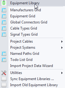
2. Access your Equipment Library. |
|
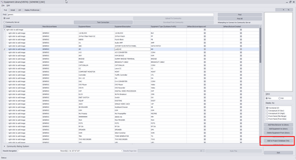
3.Find the equipment you would like to use and click [Add to Project Database Only].
Note: You can add as many pieces of equipment you as you would like at this time however you will need to have at least the 2 definitions that the Backbone are linked to. |
|
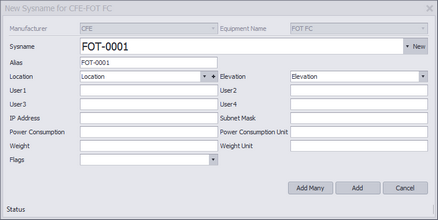
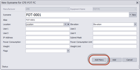
4. A new SysName window will pop up asking you to verify information about this equipment. The next available SysName will automatically populate. |
|
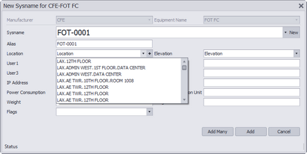
5. Enter in your location for this equipment. Example: Admin Basement Telephone Room. |
|
6. If there are multiple pieces of the same equipment in this location, you can select the [Add Many] to create multiple pieces of equipment at the same time.
Note: WireCAD will automatically SysName each piece of equipment using the next available number in the sequence. |
|
7. Once you have added your equipment into the Project Database, close your Equipment Library. |
|
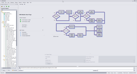
8. Enter ABS into the command line and press enter or click on the [Add Backbone] button on the homepage. |
|
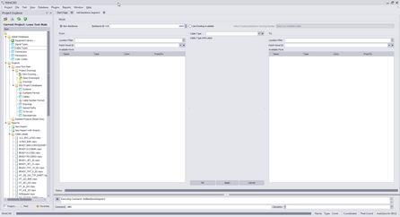
9. The Add Backbone Segment window should now be open. |
|
10. First select if you would like to create a New Backbone or Use Existing Available. |
|
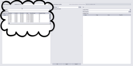
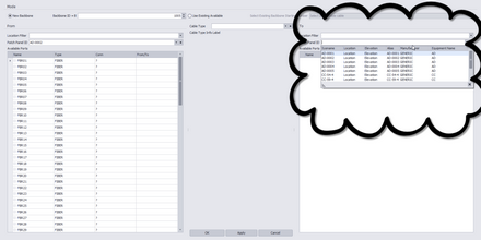
11. On the From side, select your equipment from the Patch Panel ID field.
Note: You can filter your results using the Location Filter field. This allows you to select only equipment listed in a location that was specified during SysName Assignment. |
|
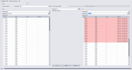
12. On the To side, select your equipment from the Patch Panel ID field. Again, you can filter your results using the Location Filter Field. |
|
13. On both sides, ports that are available will be shown in white while ports that are currently being used will show as pink. |
|
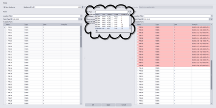
14. From the Cable Type field, select the Cable Type you would like to use as your backbone.
Note: If you have not already created a Cable Type for your backbone, you can do so by clicking the [+] sign and following the instructions here. |
|
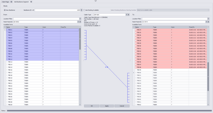
15. Select the ports you would like to use on the From side, then select a starting port on the To side.
Note: You will see that WireCAD will automatically draw a backbone based on your port selection and Cable Strand count. NOTE: See * Below! |
|
16. Click [Apply]. WireCAD will create this backbone and then revert to an empty page ready for another backbone assignment. |
|
*Note: Always make sure that you are not overlaying on used ports and that the ports coming in are not the same as the ports going out. Example: If you have a Patch Panel with 24 Ports in and 24 Ports out, you could use ports 1-12 as your incoming ports and 13-24 as your output ports. This allows the other 12 ports on each side to be used for jumpers to other equipment while maintaining a backbone infrastructure. |
|